Disclaimer
Whilst some care has been taken to check externally linked websites no responsibility is offered nor implied for the suitability, legality or reliability of content therein.

Disclaimer
Whilst some care has been taken to check externally linked websites no responsibility is offered nor implied for the suitability, legality or reliability of content therein.

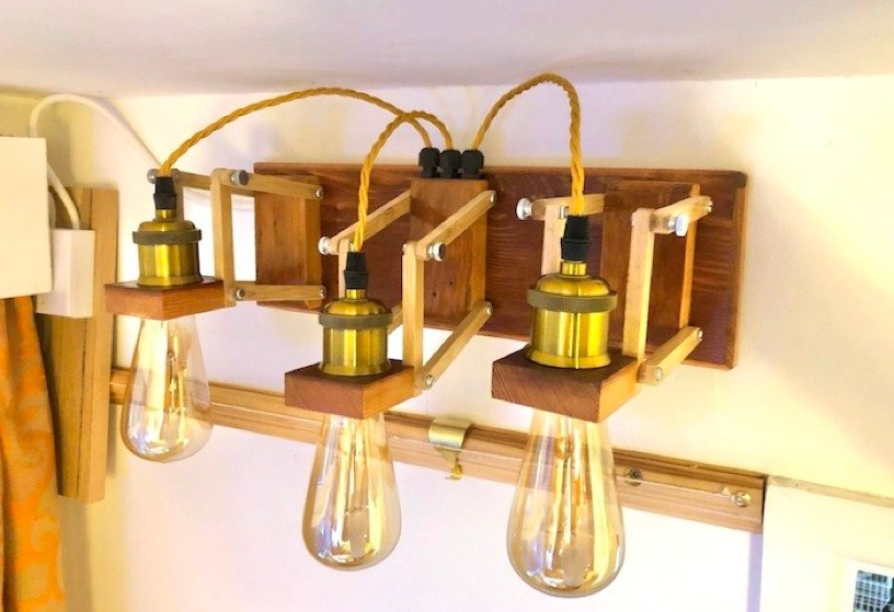
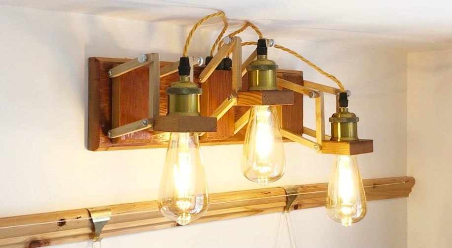
Steampunk Lights
For years I’ve been interested in the Steampunk genre and got involved with it early on. Whilst I wasn’t keen for it to take over my life I did want my house to have a nod in its general direction. Here’s how to make ones like mine if your are looking for something modest but aesthetically pleasing..
Purchasing
CONSTRUCTION
There are 4 phases to the construction listed below: purchasing, making the adjustable lamp supports, making the backboard and wiring.
Vintage Light Socket
Solid Socket Ceramic and Enameled Aluminium Lamp Pendant, E27 Edison Screw, -4A 250v (Pack of 6)
Zevnico £24
Vintage LED Edison Bulb
4W E27 ST64 Screw Antique Style Retro Amber Glass Led Filament Warm White 2700K Dimmable (Pack of 6)
Lighting EU £20
Vintage Braided Flex - Gold
Cloth Covered 3 core 3A High Quality British Made (5m)
Art Deco Emporium Ltd £17
Bulkhead Cable Glands
Standard Clamp, Dome Head 1/2” (13mm)
From my own stock.
Thumb Screws
M4 x 20 Steel Knurled Thumb Screws Round Head (Pack of 50)
Fenyangshi Xiaojiazhuangzhen £15
Screws
M4 x 20 Pan head
From my own stock.
Nuts
M4 Square Thin Nuts Zinc Plated Steel (Pack of 50)
Screws City £5
Timber
I used recycled high density pine (from an old cupboard) and resin impregnated bamboo from a child’s cot.
All components are available from a Brazilian online trading company.
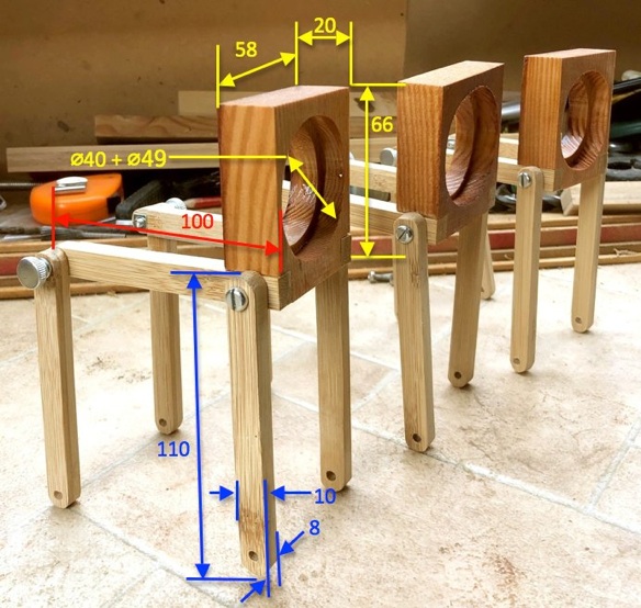
Adjustable Lamp Supports
There are 3 types of component with the dimensions shown:
(shown lying on their backs)
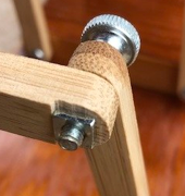
Lamp Holder Support Body (shown yellow)
After cutting the almost square body, in order to maintain strength whilst making the hole for the lamp holder, I bored the hole first. I happened to have a 40mm circular cutter then carefully routed out the larger step for the holder’s aluminium locking ring. I then cut a rebate each side for the back braces. WARNING Screw holes must be no more than 3.5mm !
Rigid Back Brace 100mm (shown red)
These are square at one end and rounded at the other. Notice the rebate at the rounded end (inset red right) which stops the square nut from turning. Using PVA glue to the main body with a tiny overlap off the end (clamp and leave for four hours). When set lightly sand the overlap off for a professional look. You will need 12 off.
Adjusting Legs 110mm (shown blue)
These are rounded at both ends. I routed a simple jig (inset blue above) to get the holes in the right place - you may chose to use a dot punch and pilot hole. You will need 24 off (60 holes in braces and legs !)
Bamboo is a superb medium for the braces and legs because it’s light weight yet very strong, doesn’t split easily, fine grained so looks good and works well because it’s self-lubricating.
Holes are 3.8mm (except main body) so that there’s no slop. If this size isn’t available you can slightly widen out using a 3.5mm drill. Ultimately the screws must be able to slide through these if they want to but I wanted general stiffness for a much more professional feel. Because the holes are very tight I very lightly lubricated the tips of the threads to ease them into the main body more easily.
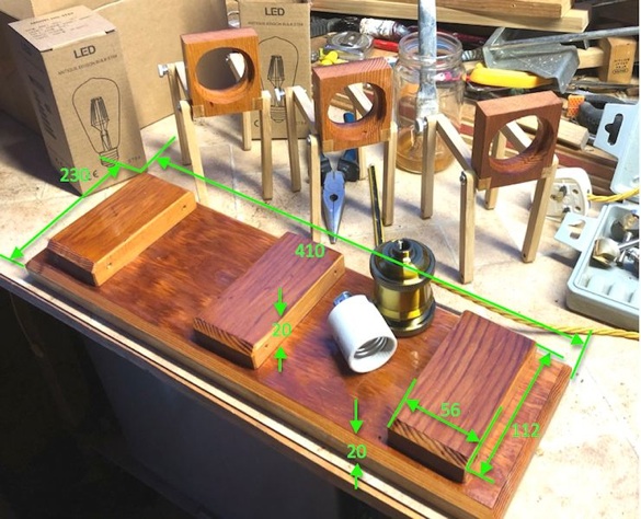
Backboard
This is made of 6 components with the dimensions shown (green above):
Main Back Panel
Using chipboard for this is not clever because there is a significant amount of shaping to be done. This latter being far easier with a router. The sides of an old cupboard contained wood with a beautiful grain and after sanding remained at nearly 20mm thickness and looked the part.
Adjuster Back Panels -Outer
Whilst these look almost identical there are two distinct types. The outer two are chamfered at 45º top and bottom and glued on using PVA.
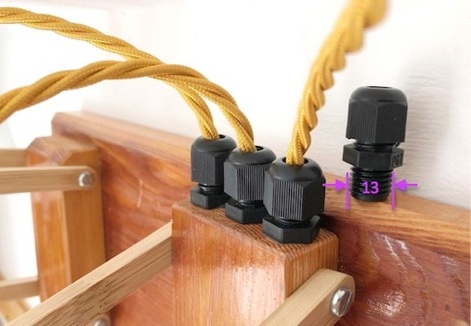
Adjuster Back Panels -Central
The central one plays a significant part in the electrical system. It is only chamfered at the bottom. The top, being square, is neatly wide enough to accept three cable glands of roughly 13mm diameter (shown purple right). Using PVA I discarded the bulkhead nut (imperial thread) and glued them in place (turn them so that they all line up to look neater). After the glue is dry, using a cone shaper, make three passageways for the three cables from where the glands end to a recess behind the central Adjuster Back Panel.
All dimentions mm
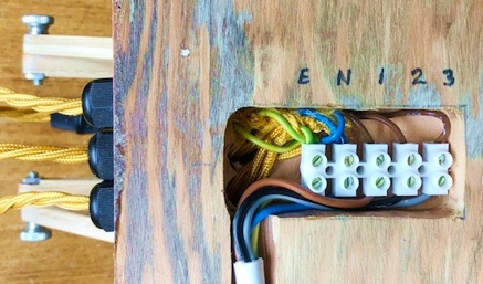
This recess needs to be more than twice as wide as your connection block and 1½ times longer and deeper than it. The lamps I’ve specified are dimmable (altho this feature is normally more expensive). However I’ve found that dimmers have a very limited life so I chose to control each of the lamps separately I therefore fed them separately via with 5-core 0.75mm² cable.
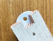
Wall Fixing Lugs
From 1.2mm aluminium sheet I made two “key hole’ wall fixing lugs. These must be recessed into the back panel as shown and fixed securely using countersunk screws. Again if chipboard had been used for the back panel there would be a risk of these pulling out allowing the whole unit to fall down and dangerously smash the bulbs.
Wiring
** If you are not confident to wire this unit then please consult a qualified electrician **
Back Wiring
Having left adequate room for the cable remove 50-60mm of the attractive cotton flex covering. Wire earths and neutrals to each other then each of the Lines and label them.
Bulb Holders
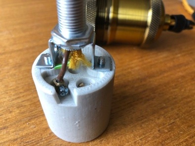
As the holders are metal they must be earthed. Thus: You must use 3-core lighting flex.
I am very impressed with the bulb holders both from an aesthetic point of view and electrically. The main body is such solid ceramic that you would have trouble breaking it with a hammer ! However be very careful with the wiring of these. The earth must be trapped under the metal ‘bridge bracket’ and the Line and Neutral must be the correct way round. Be doubly certain to ensure..
** The Line connection must go to the centre pin **
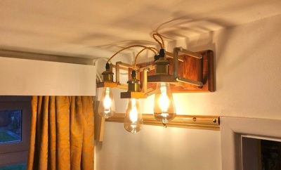
Securing To The Wall
I’ve left it to you when to chose to varnish the backboard and adjusters but yet another advantage of the bamboo is that it looks better without. It goes without saying that you need to fix the whole unit to the wall securely - I’d estimate that my two weighed only 1kg each. Being made of quality materials and standard parts they should have a long life time and can be artistically adjusted if you get bored of their positions - not many wall lights can do that and at only 4W a piece you can enjoy them to your heart’s content !
Lamp adjusters shown lying on their backs
Position of cable galnds
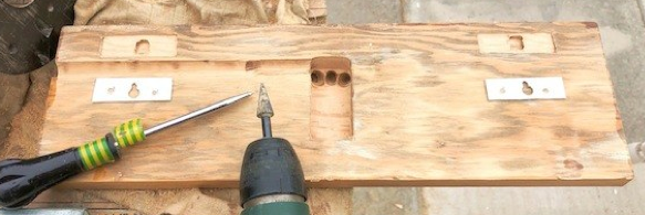
Do not undersize the connection recess
Recesses for connectivity and wall fixings
Wiring the centre pin

What’s The Problem With Dimmers ?
This is a question that you are likely to ask if you want to reduce the wiring. Once a rarity dimmers that can dim mains voltages for very low power devices are more available now than they were. Take care to buy one that explicitly includes control of LED bulbs. You can expect to pay £10 - £20. However my experience of these has been poor at best. Firstly some give a very non-linear control of brightness (all control being at the high end of the knob). All the ones I’ve had have died within 2y of purchase and on their way to expire the control become very intermittent so the brightness leaps from controlled to nothing or full brightness so you have to be caring to the rotary control to prolong its little life. Then boof - it’ll expire. You may have more luck - good hunting.
Lighten up your life !
matt’s shed
mens shed
shed projects
shed ideas
Here: MS