Portable Appliance Testing

4. Types Of Low Risk Equipment And Appliances And Their Testing
New Appliances Or Installations
Because the quality of manufacturing may vary minimum British Regulations and British Standards are published. Before any appliance can be sold or installed it must comply and be tested after manufacture against these standards. The following publications exist. You must normally pay for these however at the time of writing this website the following links appear to be free of charge;
PA Testing
You may be surprised to read that PAT testing is NOT British law. However it becomes a criminal offense if one person kills or injures another either deliberately or accidentally. In calculating blame if you are seen to be negligent consciously or otherwise then you are subject to criminal punishments in a court of law.
It follows that if you did not take reasonable steps to prevent the incident then you contributed to it. Testing is a reasonable step.
Reasonable Precautions
Should a tragic occurrence happen:
the first thing a judge will ask is: “What reasonable precautions did you take to avoid the incident ?”
Of course where hazards are involved we can be reasonably expected to pre-empt a failure or bad manufacture by testing what we plug into the mains supply.
Introduction
With so many electrical needs in our society never before has there been a greater need for us to ensure that devices that we plug into mains power are proven to be safe. I’ve been electrocuted and survived. How much more careful do we need to be with people whose bodies are not so resilient.
By testing our portable appliances we will protect the loved ones that we know and those of people coming into contact with us. We have legal duty to do so when using or providing services to the public, schools or colleges, hired venues or outside activities. Not only, it is common sense that we take steps to minimise risk.

1. The Law
2. Standards For New Appliances
4.1 Fixed Distribution Equipment
Any item of fixed distribution equipment which is part of the fabric of the building must be tested frequently. Advice is outside of the remit offered here. Please contact the owner/manager of the building.
Equipment can be considered to be of the following types:
-
•Fixed distribution equipment which is part of the fabric of a building.
-
•Ultra low voltage equipment
-
•Earthed portable equipment
-
•Not earthed portable equipment
4.2 Ultra Low Voltage Equipment
Tests have been conducted on the human body and it has been found that no significant damage can be found by application of 50v or less. Therefore sources of power below this are deemed intrinsically safe and no advice is offered here. It is notable that the quality and occasions of the use of electrical insulation is significantly relaxed in these installations. However please be aware that some ELV equipment may supply large currents either in use or if short-circuited. The consequential heat rise may then melt conductors in the vicinity causing burns or fire.
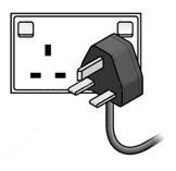
4.3 Earthed Portable Equipment - Class 1
In Britain this is the highest standard of portable equipment. All mains powered parts are prevented from being exposed. Any exposed metalwork is connected to electrical earth by a separate earthed conductor in the power lead. A fuse either in the equipment or as part of the mains lead is provided to cut off the live voltage of the supply in the event of overload (see below The Purpose Of Fuses). In the regulations given above it is rightly called Class 1 equipment and may carry the British Standard kite mark (shown right).
Should you be asked to test the equipment the following steps are reasonable:
Visual Inspections
In good light perform the following inspections:
-
•Inspect the housing of the appliance. The test should fail if: it is damaged or access to the interior, without the use of a tool eg screwdriver, is possible.
-
•Inspected the mains lead. The test should fail if: the are any splits in the outer and/or inner insulation.
-
•Inspect the cable grips of the mains lead. The test should fail if: the cable could pull out from either end of the devices it connects thereby exposing the interior.
-
•Inspect the tightness of the connections at either end of the mains lead. The test should fail if: slack connections may lead to over heating in use.
-
•Inspect the fuse. The test should fail if: there is a fuse in any conductor other than the live incoming power, if the rating of the fuse is higher than the rating of the supply cable conductor.
Electrical Tests
An approved testing device must be used to conduct these tests. Plug the portable appliance into the tester and attach the supplied crocodile clip to the largest piece of exterior metal bodywork or mounting bolts of the appliance or the output shaft if the device is a motor. If there is none then the test must be performed as Class 2 below. The appliance must be placed upon a dry, insulating, supportive surface. Do not hold the appliance whilst performing the tests. Switch all switches to the “ON” position and increase the output voltage to be above zero if the device is a power supply. In good light perform the following:
-
•Earth Test This test ensures that there is enough earth conductivity to blow this fuse in the event of a fault. It therefore follows that it must be performed at a current higher than that of the fuse used to protect the appliance. You must select one of two normal settings approx 8A or approx 25A. There are normally two thresholds of maximum earth impedance: either 0.1 ohm or 0.5 ohm. Other than short mains leads I have found it necessary to leave this set to the latter. There may be a duration setting for the test - this should normally be set to 5 seconds. To each piece of exterior metalwork, starting with the largest, attach the supplied crocodile clip and press the Earth test button. The test should fail if: there is more than your chosen value of earth impedance or you smell burning when the test is performed indicating that the earth connection is so poor that it cannot cope with a likely fault current (which in itself is dangerous).
-
•Insulation Test Leave the crocodile clip connected to any exposed metal that is most likely to be connected to any mains transformer or powered parts of the appliance. In this test 500v is applied to both live and neutral for 5 seconds (so keep your hands away). Whilst there is no net current expected to flow through the appliance during this test it does stress the insulation of all primary components to prove that they cannot break down in normal use. Move the crocodile clip round to each piece of exposed metalwork and repeat the test - including every output connection if the device is a power supply. The test should fail if: there is less than 1 megaohm of insulation from live to earth. You can understand why you should be careful to not be in contact with the device when performing the test.
-
•Flash Test If this is an option skip it because 5000v is applied briefly to the device and often modern components will break down under such stress.
-
•Earth Leakage Test This applies mains to the appliance for approx 10 seconds. In that time it is expected that the appliance will properly power up and internal power regulators and/or relays will come to their fully working state. Again with the supplied crocodile clip in place and press the Earth Leakage Test button. The test should fail if: more than 0.3mA leaks to earth during this test. It is noticeable that Residual Current Breakers are tolerant up to 30mA. However this test ensures that external capacitances cannot charge up as a result of leakage of power to the body of the appliance.
-
•Function Test If your appliance has no indicator how do you know that it works ? More importantly how do you know that the appliance was properly tested internally and externally without seeing an indicator come on during the Earth Leakage Test when the appliance is powered ? The sad thing is if you performed the above tests and really there was a break in the means leads somehow which prevented the appliance from working all the above tests would pass yet not all was tested ! Oh dear. Therefore if there’s no indicator, when the tests are complete, you must plug the appliance into the mains and use it to prove that the mains wiring, internal and external, is functional and therefore the tests above proved all the wiring was safe. If you don’t and the wiring suddenly starts working and there’s a fault you have the potential for a fatal accident.
Electrical Tests
An approved testing device must be used to conduct these tests. Plug the portable appliance into the tester and attach the supplied crocodile clip to the largest piece of exterior metal bodywork or the output shaft if the device is a motor. The appliance must be placed upon a dry, insulating, supportive surface. Do not hold the appliance whilst performing the tests. Switch all switches to the “ON” position and increase the output voltage to be above zero if the device is a power supply. In good light perform the following:
-
•Insulation Test Leave the crocodile clip connected to any exposed metal that is most likely to be connected to any mains transformer of powered parts of the appliance. In this test 600v is applied to both live and neutral for 5 seconds (so keep your hands away). Whilst there is no net current expected to flow through the appliance during this test it does stress the insulation of all primary components to prove that they cannot break down in normal use. Move the crocodile clip round to each piece of exposed metalwork and repeat the test - including every output connection if the device is a power supply or audio device. The test should fail if: there is less than 1 megaohm of insulation from live to earth.
-
•Flash Test If this is an option on your tester DO NOT PERFORM THIS TEST because 5000v is applied briefly to the device and often modern components will break down under such stress.
-
•Earth Leakage Test This applies mains to the appliance for approx 10seconds. In that time it is expected that the appliance will properly power up and internal power regulators and/or relays will come to their fully working state. Again with the supplied crocodile clip in place press the Earth Leakage Test button. The test should fail if: more than 0.3mA leaks to earth during this test. It is noticeable that Residual Current Breakers are tolerant up to 30mA. However this test ensures that external capacitances cannot charge up as a result of leakage of power to the body of the appliance and later give someone a shock.
-
•Function Test If your appliance has no indicator how do you know that it works ? More importantly how do you know that the appliance was properly tested internally and externally without seeing an indicator come on during the Earth Leakage Test when the appliance is powered ? The sad thing is if you performed the above tests and really there was a break in the means leads somehow which prevented the appliance from working all the above tests would pass yet not all was tested ! Oh dear. Therefore if there’s no indicator, when the tests are complete, you must plug the appliance into the mains and use it to prove that the mains wiring, internal and external, is functional and therefore the tests above proved all the wiring was safe. If you don’t and the wiring suddenly starts working and there’s a fault you have the potential for a fatal accident.
4.4 not earthed Portable Equipment - Class 2
In Britain this is a compromised standard for cheap portable equipment. It is allowable though. All mains powered parts are double insulated from becoming exposed internally or to connect to the external metalwork. No connection is made to electrical earth in the power lead -it will contain merely two conductors (not three as Class1). A fuse either in the equipment or as part of the mains lead is provided to cut off the live voltage of the supply in the event of overload (see below The Purpose Of Fuses). In the regulations given above to comply it must carry the Double Insulation symbol (shown right).
Should you be asked to test the equipment the following steps are reasonable:
Visual Inspections
In good light perform the following inspections:
-
•Ensure that somewhere on the bodywork the appliance displays the Double Insulation symbol (this is a protected symbol and cannot be used without permission). If no symbol present then it hasn’t been made to double insulated standards and MUST FAIL THE TEST.
-
•Inspect the housing of the appliance. The test should fail if: it is damaged or access to the interior, without the use of a tool eg screwdriver, is possible.
-
•Inspected the mains lead. The test should fail if: theRE are any splits in the outer and/or inner insulation.
-
•Inspect the cable grips of the mains lead. The test should fail if: the cable could pull out from either end of the devices it connects thereby exposing the interior.
-
•Inspect the tightness of the connections at either end of the mains lead. The test should fail if: slack connections may lead to over heating in use.
-
•Inspect the fuse. The test should fail if: there is a fuse in any conductor other than the live incoming power, or if the rating of the fuse is higher than the rating of the supply cable conductor.


5. Cable Ratings
Limits Of Estimating Cables
As energy cannot be destroyed current passing through a resistance will generate heat. Copper is not a perfect conductor so has a small, but measurable, resistance. As current flows in it that heat will cause the cable to increase its temperature above ambient and the heat will move away from the conductor through the insulation. However if the cable is not in free air but insulated, as electrical cables are, then only some of the heat will dissipate naturally and the remainder will make the cable even warmer. All metals have a positive resistance/temperature coefficient and so copper’s resistance will increase as it gets hotter and so even more heat will be generated. At a certain current the whole process will self-perpetuate and run away causing the insulation to catch fire.
Those clever among you will be thinking that as the resistance has increased and so the current will be decreased proportionately. This is true. However heat production is proportional the the square of the current ie P = I²R and so run-away will indeed occur.
It is wise to avoid that. However there cannot be a general simple answer to the maximum current carrying capacity of all cables treated alike because they’re not all alike:
-
•The purity of the copper varies
-
•The thickness and thermal conductivity of the insulator varies
-
•The cable may be further surrounded by thermal insulation eg surrounded by glass wool in a cavity wall.
-
•Manufacturers claim different maximum allowable temperatures (normally 30°C above ambient which IMHO is a lot)
-
•The cable may be coiled up on itself
More Accurate Sources Of Figures
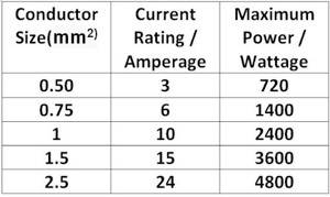
Engineers are therefore resistant (excuse the pun) to quote cable ratings. However a fairly down-graded rule of thumb looks
like this (see right)
For more accurate information you may visit: Cable ratings .co .uk
or view a manufacturer’s specifications eg Associated Electrical Industries
6. Fuses And Breakers
A fuse’s primary purpose is to prevent fire in the cable ‘down stream’ of them. Obviously as distribution of power occurs the current carried is less and cables need not be so thick. Whenever there is a change of thickness the cables downstream are protected by a fuse. In the power stations fuses may be rated at thousands of amperes, in local town distributions hundreds and in the home a few tens. In appliance mains leads fuse ratings may be just a single figure. This is called discrimination not only does it correctly protect different capacities of cable but it allows one part of a circuit to be isolated without having to remove power from the whole system.
A fuse is a piece of conductor than is thinner than the conductor that it’s protecting. Should the current demanded eg in the event of overload for whatever reason, then the fuse will burn through rather than the wire which is obviously a great benefit in preventing fire or burns to people.
If this thinner conductor should be ‘blown’ then it should installed in such a way as to be easily replaced.
Down-graded Cable Capacities
Types Of Fuses & Breakers
-
•Fuse Wire Old fuse boxes were arranged with terminals where calibrated fuse wire could be screwed into place in a ceramic insulator pod.
-
•Cartridge Fuses Still widely used today the calibrated fuse wire is mounted inside a ceramic tube filled with sand. Terminals at each end are either screwed or clip into place. The whole unit is thrown away if it blows.
-
•Circuit Breakers These can be half a meter across (I was in charge of a GEC factory making these once). They may be electrically of magnetically triggered. However the ones that we will come into contact with domestically, Miniature Circuit Breakers MCB’s, are slightly smaller than the size of a pack of cards. Groups of them are fitted into a “Consumer Unit” with their toggle switches facing outwards. If triggered the switch swings up to indicate which one has ‘blown’. Usefully they can be opened to isolate the downstream circuit should a reason dictate.
Fuses Are Poor At Saving Life
As I said a fuse’s primary purpose, upon overload, is to blow and thereby prevent fire. In this event the circuit is isolated and may preventing electrocution of people. However this is a very flawed method if the appliance becomes faulty or gets wet. Consider the two scenarios:
Class 1 Methods Of Protection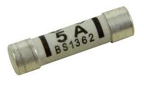
Class 1 equipment has all external metalwork earthed. In the event of certain faults the fuse may blow. Testing should be carried out envisioning the following scenarios:
-
•the fuse will only blow if the earth circuit is capable of carrying the full fault current for long enough to blow it. It follows that only by regular testing of the full earth circuit ie screws, wiring and connectors, at somewhat above the likely fault current will the reliability of the earth circuit be assured.
-
•the fuse, so easily replaced, is rated at a low value than the wiring downstream of it. This must be inspected.
If some of the live current is able to contact a human, eg when the appliance gets wet, then the fuse will not blow.
Class 2 Methods Of Protection
Only in the event of a current between live and neutral/return rising above that of the fuse rating will it be blown. For all it paucity of protection testing should be carried out envisioning the following scenarios.
-
•the unit must be inspected to ensure that it has been manufactured to Class 2 standards ie significant protection of the internal mains wiring.
-
•the fuse, so easily replaced, must be the correct rating for the wiring downstream of it
-
•any ‘leakage between live and any external metalwork is below the British Standard of 3mA.
If any of the live current is able to contact a human, eg when any of the metalwork comes into contact with the live or the appliance gets wet, then the fuse will not blow.
Residual Current Circuit Breakers Are A Good Way Of Saving Life
So to the opposite end of the spectrum. A Residual Current Circuit Breaker (see right) measures the difference in the current flowing in the live and the return halves of the circuit. If this residual current rises above 30mA for more than 30milliseconds then the toggle switch drops and both halves of the circuit are opened completely isolating all parts of the circuit (in large industrial complexes the figures are 50mA and 50mS). Thus if anything animal, vegetable or mineral imbalances the circuit it will be isolated. This is the best method of protection.
It is British law that domestic MCB’s (see above) have a RCCD action protecting all parts of the home and most work places.
Usefully the toggle switch may be thrown to isolate the circuit during maintenance.

When To Reject Cables
Coming soon.
Wear And Tear
Testing appliances when new is not the end of the story. In use existing appliances will be moved about, modified or damaged. Just every day wear and tear can compromise those minimum electrical standards. In order to provide a safe working environment regular testing is the only reasonable approach in a court of law. You may further be surprised to read that the frequency of testing is not specified in law. However if an appliance is subject to serious stress every few minutes then it follows it should be tested every few tens of minutes. If every day then every few days, weekly then monthly, monthly then annually and so on.
Regular Testing
Therefore a safety testing regime needs to be devised that is commensurate with the risk. It follows that the higher and more likely the risk then the testing must be more thorough and more frequent. It is not the remit of this web page to offer advice on this.
Nearly all public venues in the UK require appliances to be marked to say that they have been tested in accordance with an agreed regime.
3. The Frequency Of Testing & Expiry Dates

Marking Appliances With An Expiry Date
By regular testing one realises that once an appliance is tested in accordance with an agreed regime and it is passed as safe at the time of testing it will need to be tested again in the future. Given the boundaries outlined in the previous paragraph it is my strong view that the person carrying out the test is the most qualified to decide when the next test should be. Explicitly I am saying that users of the equipment are most unlikely to have the judgement of when the next test should be. It follows therefore that any label placed upon the appliance should NOT say when the test was carried out because this is meaningless to the user -a period of decades could pass before someone decides to re-test. I suggest that the label must say when the NEXT test must be and this would be based upon the tester’s professional judgement and in liaison with the management of the owners of the appliance.
The responsibility is yours. Suffice it to say that in normal risk environments the following reasonable steps may lead to safer operation of mains powered portable appliances.
Current In Circuit Using Slightly Poor Wire
I = 12V / (3 +1) Ohms = 3A
Brightness Of Lamp
P = 3A² x 3 Ohms = 27W = 56% ie half brightness !

Electricity Explained
The answer to how the percentage of full brightness of the headlamp is calculated here:


Disclaimer
Whilst some care has been taken to check externally linked websites no responsibility is offered nor implied for the suitability, legality or reliability of content therein.