G4. Calculate Regulator Resistor Values


We now have two simultaneous equations. The first one can be simplified to:

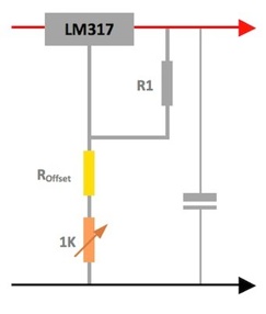
ROffset   =  R1 x (4.3/1.25 - 1)   =  R1 x 2.44


If we now substitute this into second one we can solve for R1:

1.25 x (1 + (R1 x 2.44 + 1000) / R1) = 9v   =   1.25 x (1 + 2.44 + 1000 / R1)   =   4.3 + 1250 / R1 = 9


Subtracting 4.3 from both sides we get:

1250 / R1   =  9 - 4.3  =  4.7


Rearranging to solve for R1 we get:

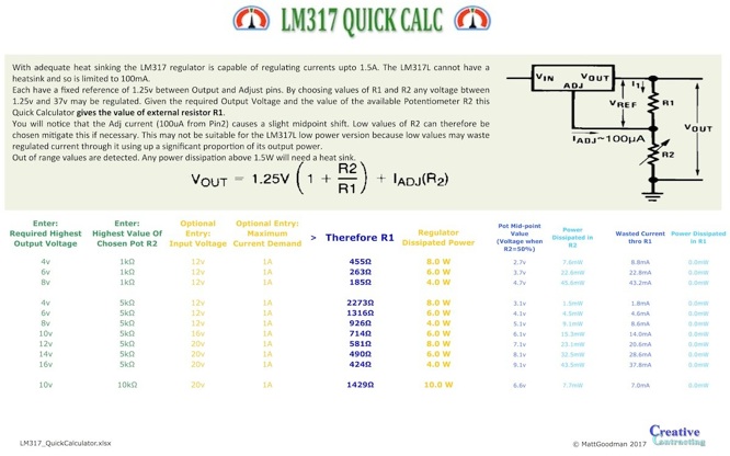
R1  = 1250 / 4.7  =  266 Ω


If we now substitute this answer into the first equation we get

ROffset   =    266 x 2.44  =  650 Ω


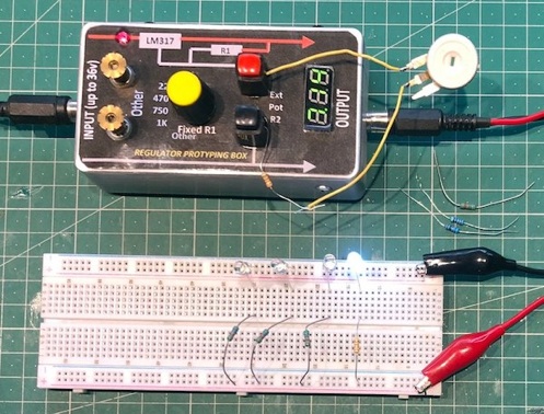
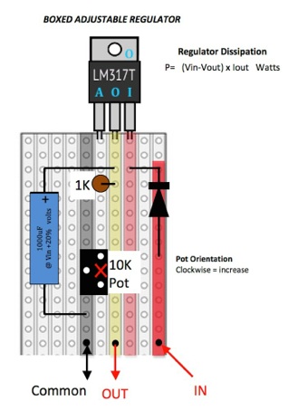
The box above facilitates this process quickly with real components.

Useful Circuits

D2. LM317 Universal Calculator

We all use these everywhere. I’m constantly placing them hither and thither so got Excel to do the calculations for me for a range of voltages and range of outputs. It’s very useful. You may download it for free by clicking it..

D. Voltage & Current Regulators

Safety

Anything electrical has the potential to do harm. Please act responsibly.

B1. Super Simple Servo System

If you need to control the position of something precisely like the selection of the gear that a model is in or the direction that the steering wheels face then a servo motor and servo control and amplification components are usually required. A long time ago I came up with a cheap closed loop control system for my models. A very good Engineer’s adage is that if it looks good it probably is.

See magazine article here:       MGE100_UniversalServoUsingAStandardDCMotor.pdf

B. Motor Control Systems

B2. Pulse Width Control Motor Control

In case you hadn’t heard: the beauty of PWM if its staggering efficiency. No heat is dissipated in the regulating power component. This is achieved by having this component either full on or full off. By varying the ratio of one to the other the power is varied to the load. The system acts just like a variable resistor only it doesn’t get hot. Using a cheap power FET is so simple that it’s the perfect solution. Please be aware that if used to control models a variable resistor provides no regulation of motor speed so if the motor is loaded it’s speed will drop and you will need to increase the output accordingly.

Here’s the circuit:              MGE101_MotorControlByPWM.pdf

Here’s the circuit layout:  MGE101_MotorControlByPWM_VeroLayout.pdf

B3. Motors & Limit Switches

A practical explanation of how to wire a motor so that it goes so far and stops yet can be brought back.

See explanation here:  MGE102_MotorCircuitWithLimitSwitches.pdf

C1. Split Power Supply For Common Earth Motor Control

Power cannot yet be sent to a motor without wires. They can be distracting to the look of a model so are best hidden. What if you could halve the number in one stroke ? Here’s how:    MGE104_SplitPowerSupply_SuitableForMotorControl.pdf

B4. Dual Speed Common Earth Control Box For Low Current Motor Control

Using power supply B1 below this box offers +9, +5, 0, -5, -9v on a common earth to any of 4 motors at the same time.

Here’s how:    MGE105_UniversalControlBox_SuitableForMotorControl.pdf

C2. A Tiny Circuit To Indicate The Fuse Condition  Of Single Or Split Supply

It’s nice to have a single indicator quickly show the first sign of where a fault lies. That could be tricky with a split supply -it’s easier than you think.

Single rail indicator:   MGE106b_FuseConditionIndicator_SingleRailPowerSupply.pdf

Split rail indicator:      MGE106a_FuseConditionIndicator_SPLITRailPowerSupply.pdf

C. Simple DC Power Supplies For Models

D1. LED Current Regulator

Putting lights on a model brings it to life. Whilst LEDs are not omnidirectional they are cheap, consistent and never ‘blow’. Simply inserting a series resistor will limit their operating current to the correct value from a fixed voltage. But what if you don’t have a fixed voltage. In reality all models are powered down a wire. If the load on that wire varies so will the voltage at the end of it. If battery powered then that terminal voltage will depend on the battery’s condition. Thus your LEDs brightness will vary.

Also it can be a pain having to solder up multiple series resistors everywhere. And if you change your supply voltage bingo you’ve got the pain of changing all those resistors which may be painted in. There surely can’t be a simple answer to this ?

There is a very simple answer: Why not think fixed current ? A LED’s brightness is based upon the current passing through it. The resistance of the P-N junction is very temperature dependent. This is why manufacturers give a range of forward voltages for a given temperature range. If you’re so used to using a voltage regulator the concept of a current regulator can’t be so foreign to you. And where do we find a jolly good current regulator in our every day box of bits ? Yes a transistor ‘collector’  is one. It requires a tiny few components and could even be made variable !


Using this method has one superb advantage: if you are using the same LEDs on a model they will each require the same current to operate them. Aha so why not wire them all in series ! And frankly with a high enough supply voltage you can add more in the chain without having to add any more components nor change the transistor ! Blimey that’s easy.

See circuit explanation:  MGE103_UniversalSmallRegulatorForLEDs.pdf

See Veroboard layout:     MGE103_UniversalSmallRegulatorForLEDs_VERO-LAYOUT.pdf

To make the light output adjustable we therefore need to build an adjustable regulator circuit. The adjustment is normally done with a variable resistor controlling a voltage regulator like the good old LM317 above.


You could just leave it at that. However a fair amount of your variable resistor’s (potentiometer or ‘pot’) adjustment is wasted just getting the circuit up from zero to where 5mA will flow. What one needs is a fixed resistor in series with the pot so that its full range produces useful adjustment. I’m really happy to do the maths for this and I find that often reality comes close to what I’ve calculated but not always and so I have to tweak the values. This is tedious so I found another, quicker way..

Obviously the answer is to prototype the circuit but I found myself leaving bits of breadboard lying about with different favourite prototype circuits on. The answer was a prototype in a box. Here’s the circuit; let’s look how it works..


E11. Regulator

You should recognise our friendly LM317 or LM317L regulator -they are virtually identical electrically. For robustness against short circuits I used the larger 1A TO220 version and bolted it to the metalwork via a mica washer and heat-transfer compound.

E12. Fixed Resistor R1

Across the regulator’s output and the Adjust pin is R1. I’ve included a rotary selector (yellow) so that a number of standard values (120R - 1K) can be switched in. However as there may occasionally be other requirements I’ve included a position for “Other”. This may be connected via two terminals (knurled brass).

E13. Adjust Potentiometer R2

Between the Adjust pin and the negative rail is R2. As in the table above R2 is the  adjustment resistor. It’s external to the box and easily connected via two loudspeaker ‘push-button’ connectors (red and black).

E14. Metering

The whole point in this is to design a circuit that works over the desired range of Output voltages so it seems eminently sensible to include a meter*. This has a micro slide switch* metering to input or output voltage.

It may seem pointless monitoring the Input voltage. However as both the LM317 and LM317L can regulate from 40v if a reasonable amount of current is being drawn then one needs to be mindful of the total power to be dissipated as heat from the device.


P =  Voltage Difference (Input -Output)   x   Output Current

E15. On/Off Switch & Smoothing

I’ve included another micro slide switch* to disconnect all the power whilst I fiddle about. The meter will produce a small amount of RF noise and it is good practice to slug the output with a small reservoir capacitor.

As with all my projects Input and Output are via audio phono (or RCA) jacks which are physically robust and if needed can carry upto 10A.

There is a ‘Power On’ LED with a series resistor which is relatively high so that 40v input could be handled.

It’s all fitted into a small aluminium Eddistone Box*.

E16. Purchasing*

I always get asked for this:

  1. Meter:  GTIWung: Voltmeter DC 0-100 0.28inch   4off £.6.69

  2. Slide Switch:  DPDT/M2 fixing  New Rise: Toggle Switch 2 position 6 pin 5mm   10off £0.88 + £0.81p&p

  3. Eddy Box: Aluminium 112x60x31mm  Lightfuture Store: Diecast Stompbox 1590BB  £5.86 + £2.02p&p.


Everything else was lying around in my storage boxes at home.

E. Regulators For LEDs:  Universal LM317 Prototyping Box

F1. Measuring A LED’s Maximum Current

To use LEDs to their full potential you will need to know the boundaries of your design. If you don’t know the maximum current that a LED can handle then it can be measured. To a stabilised variable power supply connect the following in a series circuit:

     Your unknown LED + 100R resistor + ammeter (with appropriate range eg 0-100mA)


During the test your room should not be brightly lit. With the supply output set to zero steadily increase it. Notice the exact colour of your LED. Keep going but as soon as the colour changes slightly it is over-heating so note the current and turn off immediately. The normal maximum current (let’s call it Imax) for your LED is 80% of this figure. Imax will be in the range 15-35mA. For the examples here I’ll use 24mA.


F2. Measuring A LED’s Forward Voltage

Remove the Ammeter from the circuit. Leave the LED in the circuit but replace the resistor with one calculated in the following way:


R =  20 - 2.5 / Imax  =   17.5 / Imax       (if Imax is in mA then R will be in kilo Ohms)

You are now in a position to design your regulator. Let’s assume that you are using a 12v supply which is a few meters of cable away. Let’s be realistic about cable loss so let’s assume that by the time it arrives VIn is 11.5v. Let’s now calculate the boundaries:


G1. Calculate Maximum Output Voltage That Will Be Available From Our Regulator

Nearly all regulators need 2v - 2.5v to operate so let’s be pessimistic (and allow for a little more cable loss):

VMax =  VIn - 2.5v     =  11.5v  -  2.5v   =  9v


This will be the maximum voltage that will be applied to your LED + dropper R no matter how many are connected in parallel (see below right).


G2. Calculate Size Of Series Dropper Resistor

Now use the following equation:

R =  (VOut- VForward ) /  Imax       =   (9v - 3v) / 24mA   =  250Ω


The nearest preferred value is 270R which just nicely reduces our maximum current a bit.


G3. Calculate The Regulator Minimum Output Voltage

We are aiming to drive a minimum of 5mA to each LED (see end of Section D02.) so this is given by:


VMin =    Imin   x  R   +   VForward      =   5mA x 270  +  3v   =   4.3v

F. Unknown LED:  Measurement Of  a) Maximum Current,  b) Forward Voltage

G. Designing A Regulator Circuit To Match Your LED’s

Universal LM317 Prototyping Box

As an example: if your value of Imax was 26mA then R will be 1.5K. Place this series resistor with this calculated value (chose the nearest preferred value is the accuracy of this component isn’t critical) in the circuit, ie in series with just the LED, and turn your power supply on at 20v. The LED should illuminate at maximum brightness.

Switch your ammeter to measure voltage, in the range 0-10v, and measure the forward voltage (VForward) of the LED. As mentioned before it will be in the range 2.2-3.2v. The guess in this latest calculation was 2.5v and any small error will hardly affect this forward voltage figure (try it by waggling the the power supply a bit -but don’t go mad for obvious reasons). For the examples here I’ll use 3.0v.

E1. LED Circuit Design Criteria

I happen to make a lot of mini regulated power supplies for LEDs and not just for models. All component LEDs (not power LED arrays) have a forward voltage drop of 2.2v - 3.2v. One could therefore supply these devices with the exact voltage that this implies. However manufacturers will always give a range -for good reason: because, as stated above (Section C1) they are current dependent devices. Traditionally if one wants to power several lamps at a time then one wires them in parallel. However LED’s are a bit different, as each one varies very slightly from the next, the current will take the LED of least resistance and so some will naturally be brighter than others. That’s not sensible circuit design.


Worse still is that the conductivity of silicon has a negative temperature coefficient, which is fairly steep, so temperature variations will lead to variations in their conductivity (the inverse of resistance) and therefore brightness again -this can even lead to thermal runaway. If the circuit is used outdoors then temperature naturally varies far, far more than indoors. The solution is simple: by adding a large enough series resistor one swamps out this effect stabilising the whole situation.


E2. Adjustable LED Brightness

I often want to adjust the brightness. I said that LED’s are current driven devices but their brightness in NOT linearly dependent on the current flowing through them. Although they’ll be visible to our very sensitive eyes when looking directly at them useful light output, for illumination of some object or wall, starts, not at zero but from around 5mA and can be increased right up to their maximum design limit. For coloured LEDs this is normally 20mA and for white LEDs 25-30mA.

If you want the original artwork (in MSWord 2008 format for ancient back compatibility):    RegulatorProtypingBox.docx

Our regulator circuit is going to look like this (see left) with the offset resistor shown in yellow.


This means that with the potentiometer set to zero, fully anti-clockwise, it should give out 4.3v. Using the normal equation for an LM317 we get:


VOut =  1.25 x (1 + ROffset/R1)   =  4.3v     [1]


Let’s assume that potentiometer has a range of 0 - 1K. As we turn it clockwise, increasing its value, the output voltage should also increase linearly (see graph right) until we get to 9v.

VOut =  1.25 x (1 + (ROffset + 1000) / R1)  =  9v     [2]


Checking our calculations:

VOut =  1.25 x (1 + 650/266)  =  4.3v


VOut =  1.25 x (1 + (650 + 1000) / 266) )  =  9v

So now we have all the criteria for making our regulator circuit. The box above facilitates this process but let’s look at the painful theory without the box..

A. Simple Switches

A1. Reversing Using A Split Power Supply

By far the simplest arrangement is to power your load either from the upper half or the lower half of a split power supply eg +9 - 0 -9v. If the load is connected to the earth or chassis then only one conductor to the load is necessary.


A2. Reversing Using A Single Power Supply

Most conventional power supplies have one output eg  +9v - 0. In this case a more complicated switch and two wires are required.


A3. Series Parallel Working

Occasionally one requires either full voltage or half the voltage to be supplied to a pair of loads. For this to work evenly then the loads much be equal eg two light bulbs of the same power. Again this is simply arranged. Note that when in series, as power is proportional to the Voltage squared, then the power in each load will be one quarter of full power.