Introduction

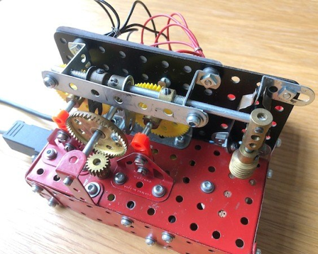
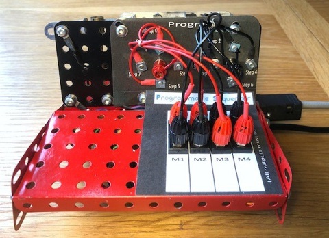
Each analog motor is switched on in whichever direction you choose until it hits a limit. This triggers the next step in your program. As you see it’s made of only a modest number of Meccano parts (although I’ve used a few proprietary connectors and a speed controller for the 2v crane motor) and the design could be extended to:  a) have fewer or more steps;  b) control fewer or more motors.


There are two tricks if you want to call them that:

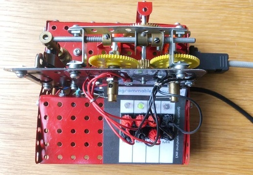
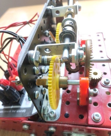
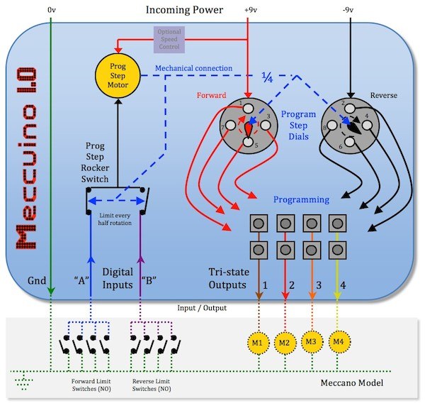
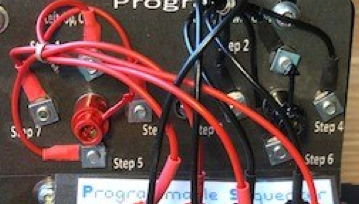
1) the two program step dials are 45° out of phase for an 8 step program. This is achieved by a half rotation of the main shaft divided by a further 4:1 reduction gearing;

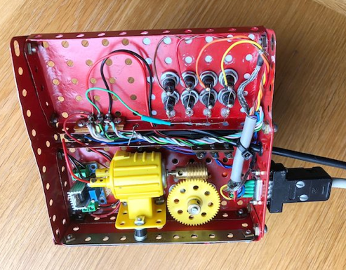
2) the motor that drives them is not constantly running but only moves when it has to (that saves power too if you’re an ultragreeny).


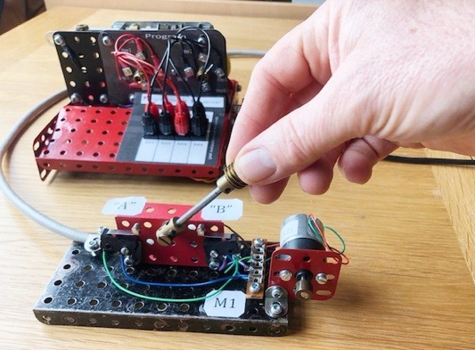
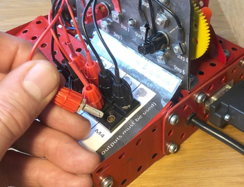
If you look carefully I happen to have fitted bicolour LEDs on the Programming board. They  show:   Red = Forward;  Green = Reverse.

(These are not shown on the circuit diagram for clarity and are unnecessary).

Disclaimer

Whilst some care has been taken to check externally linked websites no responsibility is offered nor implied for the suitability, legality or reliability of content therein.

Just what you’ve always wanted:  a mechanical Arduino !

It’s so simple I don’t know why anyone hasn’t thought of it before -I might have a word with James Dyson to get lots of them made !


I’ll use it in anger to control the Heath Robinson model that is still under construction.


Matt Goodman

March 2022

But there’s no Com Port back to a pc..    Nor even a pc !

Finally I’ve built a working Meccano prototype. Yes there’s lots of things that it doesn’t do that a real Microcontroller can but this is made of completely standard Meccano parts, can be easily programmed and doesn’t cover your model in wires. Let’s see how..

Fundamental to the understanding of the operation of this unit is that it runs off a split power supply. That is one side of each motor is earthed/0v. The other side will be supplied by +9v or -9v or not connected at all.


(See Section B1 on the page Useful Circuits)

Program

Stepper

Motor

Programming the unit consists of placing plug in a socket.


Sockets - Drive Outputs To Motors

My model needs 4 motors to be controlled and each motor will operate once and come back once. That is 8 permutations. I have therefore provided 8 sockets, arranged in 4 pairs. If you look at the underside of the unit (below) you will see that the sockets are connected together in columns -each pair is connected to a motor.


For convenience I have labelled them M1 - M4 and left a blank space below the label to write what actual function that motor performs eg “Hook up/down”.


It is perfectly feasible to have any motor operate more than once and come back more than once. One would then need more pairs of sockets connected vertically. It is also perfectly feasible to control more motors. One would then need more columns of sockets. Both of these scenarios will likely need more program steps.

Programming

Plugs: Program Steps: Labelled 1 to 8

Each plug represents the results of a program step. They alternate Red (for forwards) and Black (for reverse). There must be equal numbers of them because each movement is expected to operate at some point and come back to where it was at some point.


The two dials are also red and black and represent program flow. They rotate clockwise simultaneously at the same speed. They indicate where an electrical contact ‘wiper’ is on the far side of the dial. However, as described above, because there are 8 steps in the program the black pointer must lag the red pointer by 45°. Each of the two dials has four staging points - hence there are 8 staging points in total. If the Program Step Motor ran continuously the wiper on the back of each dial would first meet a Red stage then a Black then a Red then a Black etc until it came back to the start. These are therefore labelled “Step 1” to “Step 8”. You’ve got it now because you know what I’m going to say: The odd ones are red because they are connected to +9v and the even ones are black because they are connected to -9v.


Hence each step alternates between connecting a motor to +9v then -9v -hence forward or reverse. The trick is that that these don’t have to go to the same motor -you can skip one and come back to it later !

It would be a bit stupid to send a combination of forward and reverses momentarily and continuously to each motor. Hence the Program Step Motor only operates very briefly. It is controlled by two processes. When you first build your Meccuino one process is likely to say program Stop and one will say program Go. Stop always takes priority.


Stop At Program Step

It will not be a surprise to learn that we need to control the Program Step Motor to turn just 45°. This is achieved by the Program Step Rocker Switch (seen right). It is basically a limit switch with override. However the override is not provided by a diode (remember I promised that you need no electronic components) but by the other half of the switch.

As you can see from the circuit diagram one side of the Program Step Motor is permanently connected to the positive power rail. The other side is connected to a common midpoint -a Long Angle Bracket (shown white).

Two Electrikit wipers, which are insulated from one-another, bear on that Long Angle Bracket. If that bracket is earthed then the Program Step Motor will run.

Program Stepping

Electrikit Threaded Insulator

Long Angle Bracket

The Program Step Motor is located on the underside of the unit (seen left). After the worm reduction drive passes to a 19t pinion on top. This turns a contrate wheel clockwise (see below). On its axel is a 15t pinion which turns the two bright yellow 60t gears counter-clockwise when looking from the back. These turn the wiper and Program Step dials at a quarter of this speed and clockwise when viewed from the front.


Stopping The Program Step Motor

Now, on the contrate is a screw which acts as the Vital Peg to slide the Rocker Slider (shown bright green below) left or right via one or other of two lightly sprung single arm cranks (see purple double arrows below).

At the end of the Rocker Slider is a coupling. On it’s end is a weight (worm) to keep it hanging nicely down. Into the coupling is also screwed a threaded Electrikit Insulator that can just nicely disconnect an Electrikit Wiper (shown dark green) from the Long Angle Bracket. Depending on whether the Rocker Slider goes left or right, from its central position, either one or other of the Electrikit Wipers will be lifted from the Long Angle Bracket.

The wipers are connected to circuits “A” and “B”. Frankly it doesn’t matter which way round but once you decide stick to it if you make more Meccuinos. Looking from the front I made the left hand one “A”.

In this way if one arranges that only “A” or “B” are earthed at any one time each half rotation of the contrate will stop the Program Step Motor and as there is a 4:1 reduction the dials will only turn 45° each time. Voilà.


Well done. Understanding all this  -it’s now time for you to go have a cup of tea....

The Vital Peg that will slightly move one or other single arm cranks to stop the Program Stepper Motor

Rocker Slider

You’ve now had your cup of tea and so let’s recap..


Two hair springs keep the Rocker Slider central. However it will never remain in that position because that means that the Program Step Motor is allowed to run. This continues until it is pushed to one end, say end “A”, therefore stopping the motor and disabling circuit “A”. However if by some quirk circuit “B” was to be earthed all will burst into life again until circuit “B” becomes disabled.


Great. You’ve got it but there’s no need to remember how - just know that it works !

Rocker Slider

Feedback To Keep Model And Program In Sync

The aim of this whole process is that our program should tell the model what to do NEXT. Right, so where do we get that Next signal from ? Yes, you’ve guessed it.. we arrange for each model movement to close a limit switch and we ensure that those limit switch closures alternately earth Circuit “A” or “B”. That’s not difficult knowing what order things will move in.


So all that remains is to put the plugs in the right holes and off we go.


  You thought this bit would be difficult but it isn’t..

Sending The Power To The Motors

To the right you can almost see a collar with part of a thin/flimsey Electrikit wiper soldered to it (shown blue. This is a sort of vandalism but it keeps things small although it doesn’t have to be done this way). As the Program Step dials turn the wiper will contact one of four round headed 5/32” bolts (shown brown, right). The wiper axel picks up it’s power from a hair spring (shown pink) which bears on a washer with a small wire soldered to it carrying either +9v or -9v. (It doesn’t have to be soldered. The pressure of the spring on the wire wrapped round the axel could work -this is a tight space).

As the wipers are at our favourite 45° out of phase only one or other wiper will make contact with a bolt head each time the Program Step Motor stops. Thus only one of the eight program plugs will ever get power at any one time (It is imperative that the wipers must operate “break before make” electrically otherwise we’ll get a short circuit at some point).

Wiper

Demonstration

Just to keep you on your toes:       Q) What’s wrong with this programming ?

Quiz Answer
Motors M3 or M4 will reach one end never to return. Always give each motor a Red and Black program output then all will be well with your model.

1. Your idea is too simplistic - I want to have several motors go forward one after the other and then for each to come back one

after the other eg all sections of a robot arm reaching out then coming back. Your idea doesn’t allow for that ?

Well, actually it does. Just because the Program Step Outputs alternate between Red and Black at each step who is to say that -9v has to be be reaching in again ? By reversing the polarity of some of the motors (which I dare say are arbitrary anyway) then the first program steps can cause each arm section to reach out. Then the final steps can bring the arm in. And, beautifully, the sections do NOT have to come back in the same order that they went out in -according to your programming. Thus your arm might make a circular motion !

FAQs

3. What if, by my complex programming, sometimes I need a limit switch to be on Circuit “A” and sometimes on Circuit “B” ?

I can only envisage this occurring in one special circumstance. When that is the case it will be predictable. It will occur when another motor has reached it’s correct position -one must then use that to operate a relay to change the attribution of that particular limit switch from Circuit “A” to Circuit “B” at that time. This will be rare.

should put up with a bit of resistance here and there (where I’ve used a simple Chinese voltage regulator to drop from +9v to 2.2v, for the crane motor, that will improve immunity too). The best way of finding the problem is to get a wire with a croc clip on each end and try ‘bridging’ one bit of chassis to another with it until you find the unreliable spot. Then add a star washer between the two parts of the unreliably conductive bolted bits of chassis. Or, of course, just run a special earth wire all the way out there (I was trying to avoid that for my model)

4. How do I increase the number of program steps ?

This is not as difficult as you might imagine. Obviously it’s only sensible to increase in even numbered amounts. You should make the following modifications:

  1. a)Increase the number of Program Stage Studs and therefore Red & Black programming plugs. This can be done by using insulated discs with the correct number of holes in eg six hole insulating Electrikit bush wheels.

  2. b)You must ensure that the wiper operation is always “break before make”

  3. c)You must increase the gearing between the Program Step Motor and the Program Dials eg to 6:1 or whatever you have chosen.

Quiz Question ?

At a recent Meccano meeting (MMG in Baginton) I demonstrated it working with one motor and one pair of limit switches.


The weighted lever demonstration proves:

  1. 1.That the whole unit is very simple.

  2. 2.That the wiring is simple and frankly could run off any voltage (up to say 50v with my little Chinese regulator) and is completely immune to dodgy power supplies.

  3. 3.That any motor is controlled by one wire only. The other terminal is earthed.

  4. 4.That any model motor keeps running until an end limit switch permanently closes NOT opens as normal limit switches do.

  5. 5.That the switches earth a circuit which cuts down the wiring and means that the contributors to “A” and “B” can all be connected together (OR’ed).

  6. 6.That when that happens the program goes to the next step and waits.

  7. 7.That the movement through the program is very visible -see the rotation of the dials (and in my case by the change in colour of the LEDs)

  8. 8.That the program can be changed whilst it is running !


What’s not to like !

Program Stage Bolts

Hair Spring

Good luck and have fun !

☕︎

= = = = = = = = = = = = = = = = = = = = = =                 = = = = = = = = = = = = = = = = = = = = = = = =

By The Way

For those that are wondering why this is Version 1.0 I am planning to replace the programming plug board with a small removable plate with the programming on. This effectively becomes a “Memstick” and means that it would be very quick to change programs EG your Robot Arm might pick other things up, etc..


This development, and maybe others, will come later.

2. My system runs unreliably and keeps stopping ?

This unit is too stupid to suffer RFI, spikes on the mains or even a malicious hacker but what is likely is that your chassis earth is poor. By their very nature limit switches tend to be in far off places where a chassis earth can be poor. The nice thing is that the Program Step Motor draws only a tiny current compared to your main motors so it