
Disclaimer
Whilst some care has been taken to check externally linked websites no responsibility is offered nor implied for the suitability, legality or reliability of content therein.
INTRODUCTION
Whilst many of Shelly’s devices represent good value for money setting up them up has been quite hard work - I thought the days of putting IP addresses into browsers was gone - but it’s back ! It seems that whilst the hardware has had to be fixed, manufactured and delivered the software has been shipped prematurely. Judging by the blogs there is going to have to be a complete overhaul otherwise competitors will just out-UserFriendly them. I had a need for several devices to be controlled and thinking that they can’t be that difficult to set up, after all it it’s only a single contact of a relay I bought two Shelly1’s. It’s been a learning curve and I’m not sure that I, nor they, are there yet. However let’s look at what useful things I’ve found..
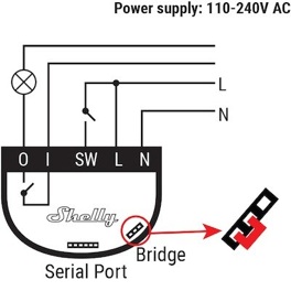
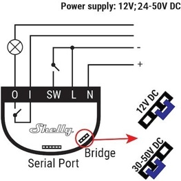
Hardware Basics Of Shelly1
COMMENTS ON PUBLISHED FEATURES
Apart from the attractive cost the website and leaflets make the following boasts to which I add these comments:
-
No Hub Required
-
Yes the Shelly 1 works perfectly well standalone. Configuration of the “SW” input is very flexible (see Local Operation Settings).
-
-
Wide Range Of Voltage Support
-
Yes they’ve covered all the common bases (see Advanced Information below).
-
DANGER
-
What is not obvious is that normally the SW pin carries half the “L” voltage and obviously if used as a trigger is connected fully to it by you eg full mains voltage. Take care !
-
-
-
Dry Contacts
-
The big selling point for me, compared to other devices, is that the output “0” and “1” are completely independent of the internal circuitry and can be connected to any voltage up to 400v with the current not exceeding a generous 16A. As these are ‘dry’ contacts it does not matter which way round “0” and “1” are used.
-
-
Designed To Fit In Most Standard Electrical Boxes And Switches
-
The device measures 18mm thick by 42mm in diameter so will even fit in a ceiling rose. Another great selling point for me is the “SW” input.
-
-
It Can Be Integrated To Work With All Other Shelly Devices
-
I’ve not done this yet.
-
-
Compatible With Android, iOS, Amazon Alexa, Google Assistant And Home Automation Servers Using MQTT, CoAP, and REST API.
-
I’ve not done this yet.
-
-
Easily Make Your Arduino Project Live And Usable In Your Automation Project
-
I’ve not done this yet.
Notice that DC supply voltage must be reversed
Advanced Information & Warnings
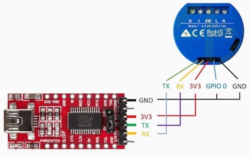
Interfacing To An External Programmer
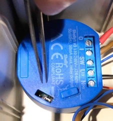
I don’t like to be a party pooper but if you are going to get really clever then you might be considering using the internal processor interface ? Indeed there are companies who will make this easy for you by supplying a gizmo to make this communications easier by converting the signals to USB compatible levels. You connect happily to the pins hidden behind the rubber cover (as shown right). However what you may not realise is that the so called “GND” pin is internally connected to the “L” pin on the screw connector block.
If you power the whole thing using the mains, as most people do:
DANGER
The USB metalwork is also live to mains !
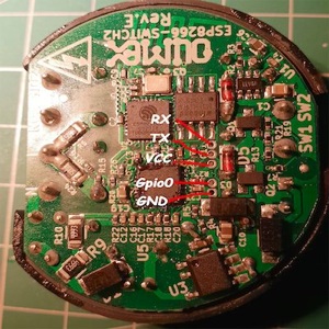
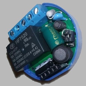
As a matter of interest here are the internals:
Internal Workings

Shelly1 Device -Network Hub Connection
Setting Up Occurs In Two Distinct Phases
Obviously follow the instructions that come with the device but here are some extra tips. Without a device to connect to you can’t do much with the app so starting with the device’s firmware:
Phase 1 Device Configuration
Wire up your Shelly carefully and switch on. You need to talk to it but you cannot do this with the app (I think that this is a major drop off but hey that’s where we are at the mo..). Using a mobile phone I did the following:
-
a)For some stupid reason the device will not talk to the outside world initially on power up as stated in the manual so perform a Factory Reset (as right). This, of course, loses all previous settings which really means that you can’t ever edit the ones that you were nearly happy with.
-
b)For a short while the device emits its own Wifi 802 access point (AP) so temporarily alter your phone settings (the manual misses stages i-ii out !):
-
i)Mobile Data -switch this off,
-
ii)Mobile Wifi Setting -search for and select “shelly1-8CAAXXXXXX” (your phone will warn that this doesn’t provide an internet connection).
-
iii)Open mobile phone browser (eg Safari) and enter 192.168.33.1 in the URL window at the top. You should now see your device’s black main Config Menu webpage (see right).
-
d)On the device’s Config Menu webpage:
-
i)If this is the first time that you have powered the device you may be requested to “Update Firmware”. Press this otherwise you may get compatibility problems with the app later.
-
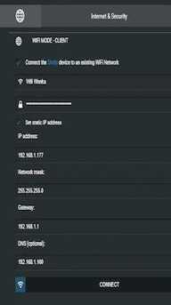
ii)Enter device’s Internet & Security (globe symbol) subpage.
-
iii)Scroll down to Wifi Mode -Client and open the dropdown (down chevron).
-
iv)Here set your network hub’s Password (first). This may be a lot of letters and numbers so I pasted it into a phone Note for copying later (yes I had to do this several times).
-
v)Then insert network hub’s Name above it (this is also known as a Service Set Identifier or SSID). The instructions tell you to press connect but my device then jumped by itself into a lockdown mode. However it had connected.
-
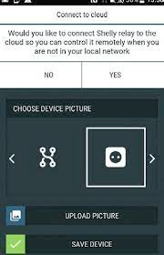
vi)Lastly you will be asked if you want the device to respond to controls from beyond your own Wifi network, that is from the internet (see far right) ? “Yes” I always do. However you may choose to keep control local only.
-
While you’re talking to the device via your web browser (confusing isn’t it ?) it’s now time to set it to work how you will want it to operate..
Factory Reset
Switch device on. Within 1 minute of doing so trigger the “SW” input 5 times slowly. You will then hear the relay jitter for a moment.
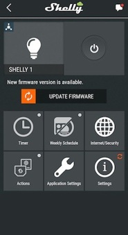
Device Config Menu
Device Internet Config
Shelly1 Device -Local Operation Settings
Phase 2 How The Device Will Operate
There are too many details to go into here to cover everything but a few things might need more explanation:
-
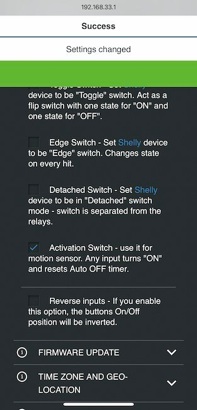
a)Button Type Config Menu The options of how the device will behave with changes to the “SW” input need clarifying. Again the language is foolish because the menu heading says “Button” but each radio option talks of a “Switch” ! What they really mean is the response when the “SW” input is asserted (ie “L” and “SW” are shorted together) by whatever means -most likely you will use contacts from another device (WARNING you must use “dry” contacts see red warning below). Here is an explanation of their explanations:
-
i)Momentary As soon as “SW” is asserted (on this leading edge) the state of the relay is reversed ie a divide by two action: if it’s Open it is closed and vice-versa.
-
ii)Toggle The relay is open normally and only for the time that “SW” is asserted is the relay is closed eg for a rocker switch to operate the relay. This is simple relay action.
-
iii)Edge -The same as Momentary above but any change in the “SW” input (both leading and trailing edges) reverse the relay. Effectively a multiply by two action.
-
iv)Detached “SW” input is ignored.
-
v)Activation This triggers the operation of the relay according to the settings in the Timer config menu. I use this mode a lot.
-
vi)Cycle This operates the relay multiple times.
-
vii)Reverse The action of the “SW” input is inverted for all modes above. For instance in Momentary the relay will be closed normally and opened when “SW” asserted.
-
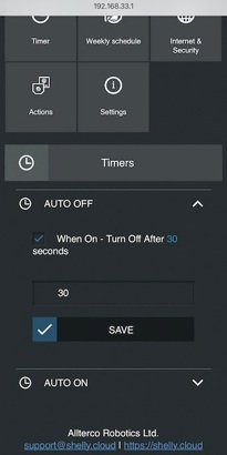
b)Timer Config Menu If you choose the “Activation” mode above (left picture) the relay will close but at some point you will want it to open ie turn the power “Off”. This can usefully be done with a Timer..
-
i)Timer: Auto Off The device will count seconds before automatically opening the relay and turning the power off.
-
ii)Timer: Auto Off The device will count seconds before automatically closing the relay and turning the power on. However if the relay was already closed, and power on, then nothing will happen. This mode would be pointless if it wasn’t for Option vii above.
If you want more pictorial information you could look at this: Review of the Shelly2.5.
Live Mains !

False Device Unavailable Error
As soon as I was confirmed the device was set up correctly I went back to the app. I included the device in a “Room” (really this should be called “Location” because mine’s in a shed operating a water pump but let’s not split hairs) and saw the error “Device Unavailable”. Nothing would solve this. Not even closing the app nor a device Factory Reset. I wasted a lot of time only to find on a blog that the app gets clogged. Closing it will not work because the “Account” remains open. However if the Log Out and Login again all comes good. Doh the flakey software again.
Troubleshooting
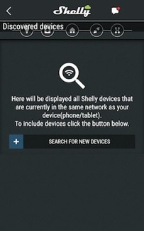
No Discovered Devices
If a device cannot be discovered by the app make sure that when setting up the device that you entered the hub Name and Password correctly. Mine jolts when connected and then freezes but the device seems to work.
After adding a new device this Search For New Devices mode has always frozen on my phone even if I log out. However if your hit the top left chevron it all appears to start working. Something flaky here but as development is on Android phones this may be just on Apple machinery !
Erroneous Names In Shelly1 Manual
The website rightly talks about the “volt free” nature of the relay contacts connected between “1” and “0”. This is a very useful feature and IT DOES NOT MATTER WHICH WAY POWER PASSES BETWEEN “1” AND “0”. However the manual very often uses phrases like “the power supply will automatically shutdown”. What they mean to say is the contacts will open. I assume that the trainee programmers weren’t talking to each other.
Allow Www Control
-
Advanced Power Information
-
It’s very clever how they’ve powered the device. My guess is that when supplying DC a diode directs the positive rail to the internal 3.3v regulator and the Bridge (see above) has a resistor placed in series if the higher voltage is in use. For AC they use this diode to half-wave rectify only the negative half cycles of the incoming AC, that is when Neutral is positive with respect to Line, and an even larger resistor in series for higher voltages. I also guess that they both use a voltage limit clamp (zener) and the same SMD voltage regulator. As I stated above be a little careful:
-
DANGER
-
What is not obvious is that normally the SW pin carries half the “L” voltage and obviously if used as a trigger is connected fully to it by you eg full mains voltage. Take care that your external contacts are volt free !
Button Config Menu

Two Steps Required
-
a)Positive To “N” and Negative To “L” The incoming power must arrive at pins which without the explanation above might seem illogical (see the microscopic (+) and (-) in left picture).
-
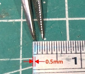
b)Move “Bridge” Handbag If you are running at 24v then leave the “Bridge” as supplied (left position). If running at 12v the dropper resistor needs to be shorted by moving the “Bridge” to the right position. I found that only the very finest of 0.5mm tweezers could reach under the rubber cover to grab the little devil (right picture).
Hardware Change For 12v Working
Timer Config Menu
Device Communications
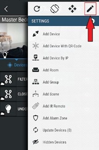
Edit Names
Edit Names
You will want to change the names that you have given the app early on. Swipe down and hit the pencil symbol at the top right (right picture).
The relay contacts “0” and “1” being ‘dry’ will also not easily transfer any electrical noise on these, eg from electric motors, onto the internal circuitry -hence the device has very good RF noise immunity.
Good Hardware Design


Internet Of Things
Shelly1: Set Up And Configuration
Internet Of Things