Stirling Engines Explained

Why Yet Another Explanation
Whilst the internet seems to be awash with people claiming to explain these beautiful machines and how to build them I was surprised at how few explain the necessary constraints of the materials necessary and to explain simply what’s going on inside which is why they work so well.
On your internet trawl you may have picked up an understanding that the principle upon which a Stirling Engine works is trivially easy. However Robert Stirling and his brother took out patents to protect their methods of harnessing this simple Physics in a sophisticated, compact and efficient manner. If you want to know the history of them then the following page is excellent: Wikipedia Stirling Engine.

Should you be looking to build either a large or small engine for yourself I will now mention the constraints that Robert and others considered in their quest for what he thought was the perfect engine. In order to do this I’m going start by looking at a small engine because many of us own one of these humble Chinese gimmicks that speed wildly on a table when placed over a cup of hot coffee. But let’s start with the constraints (in order of increasing complexity)..
-
1. First let me point out that they are a heat engine not a steam engine. They rely on the alternating expansion and contraction of a gas which is normally air.
-
2. That gas need never leave the engine. If it is air, and it does leak out, then there’s no risk in breathing it.
-
3. If the air does leak out on the expansion stroke then the contraction stroke will suck some air back in and a equilibrium ensues. Of course leaks will reduce efficiency.
-
4. There needs to be a hot part of the engine and a cold part. Thermal conduction between the two will reduce efficiency.
-
5. The larger the difference in temperature the more work that can be extracted.
-
6. It doesn’t matter which end is the hot or cold end - reversing them will merely reverse the direction of engine rotation. So a block of frozen coffee would do just as well ! Conversely, unlike any engine you ever messed with before, rotating the engine will cause a temperature difference between the two ends !
Constraints
Materials
Stirling Cycle
Overall Construction Materials
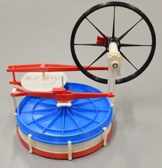
Most cheap little Stirling Engines will contain a high proportion of plastic parts and if the temperatures involved are below the melting point of the plastic eg by the use of hot water then a 3D printed Stirling Engine is perfectly feasible (example left from 3DPrint.com).
-
7. Making the hot end really hot will cause significant problems with many materials and waste energy through the usual conduction, convection or radiation !
-
8. There are two moving parts one must be a sloppy fit in its cylinder and the other must not leak in its cylinder otherwise there will, you guessed it, be a reduction in efficiency.
-
9. Stirling engines have two power strokes per rotation -sucking and blowing of the work piston.
-
10.In between power strokes a suitable flywheel is needed to maintain motion through the ‘dead-spots’.
-
11.As with all reciprocating engines, apart from the flywheel, the lighter the moving components the less energy is wasted accelerating and decelerating them and bearings need not be so sturdy.
At each end of it a Stirling engine needs to move heat from its source to the gas inside. There are specialist plastics that conduct heat reasonably well but most metals are cheap, look good and conduct heat well eg copper, brass, aluminium.
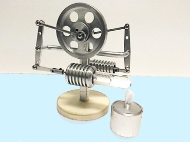
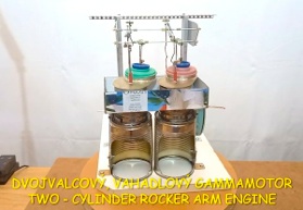
In many Stirling Engines the two mechanical jobs that need to be done are separated. In pic right:
A = Heat-cycle Cylinder
B = Work-cycle Cylinder
I will just mention here that the piston inside cylinder A must be a very sloppy fit and that in B must be gas tight. This latter can be an issue see below.
Design Compromises In this example sadly the shaping of the hot end is poor. There is another problem here because the hot and cool ends are physically close to each other and even worse they are the same physical piece of metal -at each end it is heated and cooled !
A
B
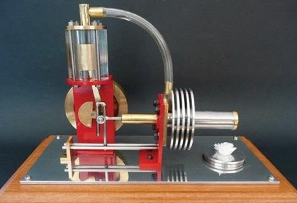
In operation one end of A needs to be kept as cool as possible so there must be some method of circulation of a coolant like water or fins can be used so that air convects between them dissipating the heat. The other end needs to be hot so it must be shaped to receive its heat efficiently.
A -Heat-Cycle Cylinder Designs Whilst the Heat-cycle Cylinder in this example isn’t ideally shaped they couldn’t sell this design if it didn’t work. The fins are either crimped or soldered to it. However I notice that the end has a brass cap which is soldered on. Solder melts at 350ºC and a flame from a liquid burner can easily reach twice that. By wasting a lot of the energy from the flame I assume that the brass end cap never gets hot enough to melt the solder !
As I said, in it the piston must be a very sloppy fit because it is merely being used to shuffle air from the hot end to the cool end and vice-versa in synchronism with the rotation of the engine. It is driven off a crank via slip-bearing C which in my humble opinion will be a source of friction. The slip-bearing reciprocates the piston via a connecting rod. The whole engine relies upon small changes in gas pressure in this cylinder so, whilst the piston itself can slop about, there must be a gas tight gland through which the connecting rod acts. Ideally this rod will move perfectly horizontally so as not to wear the gland. In reality this is not easy to achieve without causing a great deal of friction. If anything this is one of the two top hurdles to overcome to distinguish a reasonable and an excellent unit. The Rhombic linkage (right) has been devised to address this problem..
C
B -Work-Cycle Cylinder Designs This cylinder is a completely different ball game -it is very much like that of an Atmospheric Steam Engine but with a separate condenser and no valves. Stirling’s idea is simplicity itself ! Any change in air pressure in the Heat-cycle Cylinder is transferred to the top end of this cylinder by the clear plastic pipe. It makes sense that it is to the top end so that its piston’s connecting rod does not need a gas tight gland.
Unlike an Atmospheric Engine there is no venting of the cylinder -it is permanently enclosed. However, as stated above, if some air does leak out on the expansion stroke some equally will be sucked in on the compression stroke and an equilibrium will establish itself.
If the air is taken from the cool end of the Heat-cycle Cylinder then it won’t be particularly hot but again beware using plastic parts if you intend to run your engine very hot. Because of the very high pressures involved large steam engines use Piston Rings to effect a tight but moveable piston seal. However, by comparison, Stirling Engines use very very low pressures so rings are unnecessary. The temptation is thus to just place a perfectly fitting piston in this cylinder. Whilst seemingly a simple and good idea any metal can be chosen -for lightness aluminium could be a good choice. HOWEVER aluminium has one of the highest coefficients of expansion (29 x 10-6 m/m/ºC) of all metals -even if the cylinder is also made of this same metal uneven heating may cause stiffness or leaks due to looseness. At the other end of the spectrum graphite has a remarkably low coefficient of expansion (-1 x 10⁻⁶ m/m/ºC up to 300ºC rising to 1 x 10⁻⁶ m/m/ºC at 1000ºC). Its crystalline sheet structure makes it light and very slippery too -especially on glass. Therefore some small engines, setting out to have very high efficiency, use this material with great success.
Stirling Engine Types
It is well understood that there are three modes in which a Stirling Engine can operate. I’m not going to re-write a detailed description here because Ohio State University (USA) have done such an excellent job. For a their clear, thorough explanation click on the text below each of these images..
Rhombic Connecting Rod Linkage
Graphite Work-cycle Pistons
Below I will run through the timing of when and how the air is alternately heated and cooled but what’s important is that because the internal volume of the whole containment is fixed the pressure in this cylinder alternately increases and decreases as common sense tells us (this is Gay-Lussac’s Law).
Recommended Viewing
There are many YouTubes of people’s attempts to make home made Stirling Engines but not many that I’d recommend. Here are a few:
Slovakian Engineer Štefan Čontó has produced some excellent innovative designs. You’d do well to study his concepts.
If you publish your work please do him the courtesy of mentioning him as your inspiration.
Štefan Čontó’s Stirling Engine Channel
(Five parts with written commentary)


(not animated)
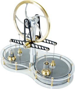
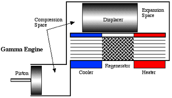
Due to their ability to work at very limited temperature difference this latter type Gamma have become very popular because they can work merely from the heat rising from a hot drink.
The cylender is being heated at the top eg by sunlight and cooled at the bottom eg by being immersed in a bath of cold water. Like most single cylinder engines this is not good at self-starting so I’m going to assume that someone has given ours a push.
From Position 1 As the crankshaft rotates the Power Piston is rising whilst the Displacer (green) is at top-dead-centre.
Position 2 shows that the Power Piston has reached top-dead-centre and moved all the cool air through the external pipe from the very bottom of the cylinder to the top where it meets a warm cylinder wall (We’ll ignore the Thermal Store at the moment).
Position 3 The air is warmed and tries to expand. The only way that can happen is to push the Power Piston down (leakage round the displacer doesn’t matter at all. You can see on the third graph that the volume increases. The shape of the graph is not linear because it takes energy to expand a gas and so the temperature falls a little (Charles Law). This is the first power stroke.
Position 4 As the flywheel turns the Displacer rises upwards forcing the hot air downwards (back through the pipe) where it cools.
Postion 1 Again The cool cylinder at the bottom shrinks the air and so the atmosphere pushes the Power Piston up. This is the second power stroke. You will notice that the graph is a curve again -by conservation of energy as a gas shrinks heat is released. Thus the flywheel gets two pushes for each complete turn of the crankshaft. This is very efficient.
Efficiency Increased Further As you can see the air, totally enclosed, never leaves the whole unit. It is merely shuffled between hot and cold. Suddenly changing the air temperature takes time and you would get a temperature gradient across the cylinder so not all of it would be fully expanded. If we pass that air through a Thermal Store we can collect the heat and recycle it to warm the air on it’s journey back upwards soon afterwards. Hence stainless steel wire or metal baffles are used to great effect.
Technical Analysis
If you are a student of thermodynamics then an analysis of the three types of Stirling Engine above is offered by OSU. However be aware, if my understanding of these complexities is correct and I may well be wrong, that there may be some assumptions that are made. If you want a general solution then these assumptions are only valid in certain circumstances so be careful to ensure that you realise where these boundaries are. See OSU: Stirling Cycle Machine Analysis by Israel Urieli.
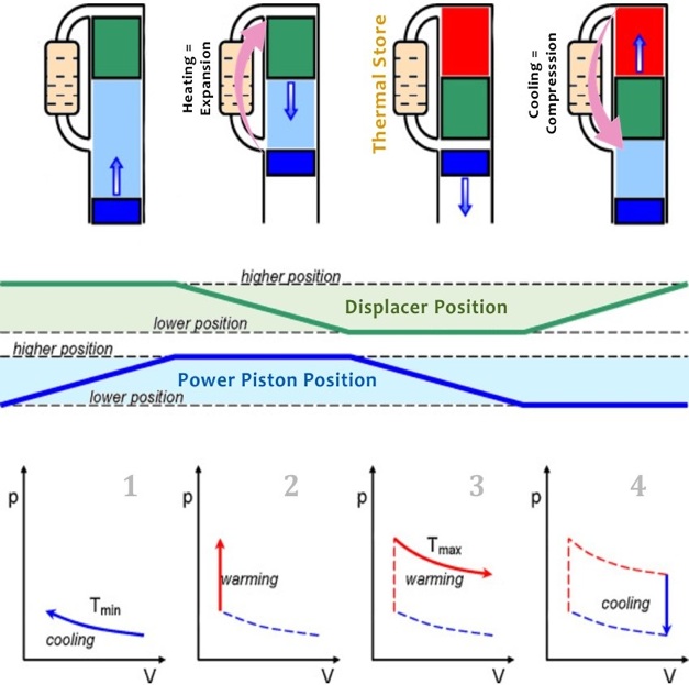
Diagram Credit
This diagram is a modified version of Figure 6 here: www.researchgate.net/figure/The-ideal-cycle-of-the-Stirling-engine_fig6_287373200
Alternative Explanations
If you have not followed this explanation then apart from OSU’s excellent mathematics the following may be useful:
Mechanical Boost Stirling Engine.com Explain That Stuff Yanmar Advanced Engine Designs
In order to describe the Stirling Cycle I’m going to use the example of a hybrid of the Alpha and Beta Stirling Engine configurations where the displacer is a reasonable fit in the cylinder so that much of the air that is displaced to the other half is via an external pipe which contains a Thermal Store (see below).
Sources Of Materials
Coming soon...
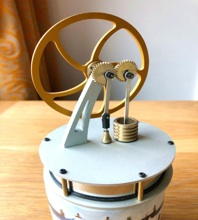
My Gamma Stirling Engine


Disclaimer
Whilst some care has been taken to check externally linked websites no responsibility is offered nor implied for the suitability, legality or reliability of content therein.